| For me, the joy in radio collecting is in hearing the old-timers working, but it is not always easy to restore them to life.
Original replacement parts are never easy to locate sometimes quite impossible. Is it better to replace the component that does the job
but does not look right or leave the set in original but not operational condition? There is another alternative, that of hiding modern
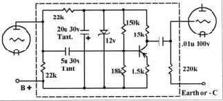
components in the old casing. the choice is up to you. I recently obtained a Hartman "Compact six" of 1927 vintage. This set is American, beautifully built, and has a cast panel which is shaped to fit the components. Both audio transformers were open circuit, and nothing I had would fit the panel without hacking it up. I decided to try an approach that was suggested in the "Antique Wireless Association of America's "Old Timers Bulletin" back in March 1982 by George A Capen . He used a transistor amplifier fitted inside the old casing and needed no changes to the receiver wiring. A 22k resistor substitutes for the transformer primary winding and the voltage drop across this resistor is filtered to remove the to remove the audio signal by R2,C2 and stabilised be zener D1 to give a 12v supply for the transistor amplifier. this amplifier is quite conventional and uses a PNP transistor. I used a BC558 but any small signal PNP transistor would be suitable. Assembled on a piece of veroboard around 25X30mm, the entire assembly easily fitted inside the old case and externally the set looks quite original. The overall gain is about the same as the tube plus transformer combination but you might need to increase the plate voltage slightly to ensure that there is 20 volts drop across the plate resistor R1 to maintain the transistor operating voltage at 12 volts. | This approach worked out fine for the first audio transformer and may have worked also for the second, but a 12v supply will
only allow something less peak to peak signal across the collector resistor R4, and I was afraid that this would not be sufficient to
fully drive the output valve without distortion. I decided to try another approach to replace the second transformer which originally
was a 2 :1step up transformer. At one of our meetings I was given a couple of very small power transformers intended for mounting on
a printed circuit board These had two primary windings intended to be wired in parallel for 110v supply and series for 220 volts.
There was also a low voltage winding that did not interest me. Again I used a 22k plate supply resistor and capacity
coupled to the centre tapped 220v winding using a .047u 600v polyester capacitor. The transformer is wired
as an autotransformer with a 2:1 step up in voltage. As there is no dc flowing through its winding the frequency response is
better than one would expect and the grid circuit impedance is lower than with the transistor amplifier.
The Hartman is now working fine and only by using an ohm meter can you tell that the transformers are not what they seem to be.
Ray Kelly |
|
| For information on the Historical Radio Society of Australia Inc. checkout their web site : |